The History of My Project

I saw an experiment on a vido entiled Fractals an Animated Discussion made in 1990, a film by H. O. Peitgen, H. Jargens, D. Sampe, and C. Zahlten. They demonstraited Choas Therory using a megnetic ball pingelum hovering over three magnets and observing which magnet would win out over the others.


a toy model of a Chaos Attractor


Using a magnetic pengelum, hovering over multiple magnets, I will record and generate a picture of a chaotic attractor.

 

Materials:

This is a list of materials I found to build my version of a Chaos Attractor

1) a 24"x 24" peice of pine plywood as a base

2) 3 pressure treated plywood blocks 4"x 4" x 4" as suport for the base

3) a 75 pound hook screw

4) a 4.5 " tube with loop top

5) two table legs with screws 1) a 15" leg measuring 1.5" x 1.5" x 1.5" 2) a 6" leg also measuring

1.5" x 1.5" x 1.5"

6) iron filings and 3 magnets with plastic handles

7) bracing material 12" x 12" x 12" (various langths)

Alterations

I cut the 24" x 24" plywood to an 18" x 18" square. I drilled a 5/8th's inch hole in the base and the two tables legs. The bolts that came prefabricated inside the table legs were removed and scrows were used to attach all the pieces along with carpenters glue. Bracing material was not needed at this point.

A pictue of my chaos attractor and the magnets that I am using.

A pictue of the magnet pendulum.


Results!!!!!

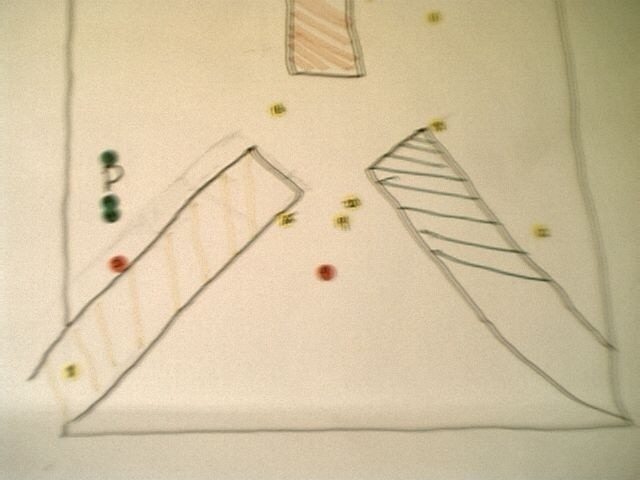
Trial one consisted of 21 plotted points of various colors (yellow, orange, and green reprisenting the colors of the bar magnets). The graphic representation of the data reflected a normal expected fractal like design. Trial two was completely different. The difference was I moved the magnets closer.

The layout of the magnets for both trials from the top down.

I discovered that by moving the magnets closer together the orage magnet became dominant. The green and yellow magnets appeared to conteract eachothers polarity. In both tests I had to also contend with the magnet periodically hitting the post. This comtraaption that I made lives up to its name as a Chaotic attractor dispite having some complications. To fix this complication the pendulum would have to be dangling from the top lige a cage like encloser where the suporting members could not effect the pendulums range of motion.

Data was presented to the class graphed on posterboard as part of the final class presentation and is shown below.

Trial 1 (yellow, green, and orage dots represent the magnet that the prendulum ended up on from that starting position. The dased lines represent the magnets. (refur to the layout picture for the position of the magnets)

Trial 2

A Graphic representation of my own data presented in class (above)


Return to the index page